Typical Process Design Sharing - Blade Category Castings
Blog post description.
heweifeng
12/10/20254 min read
Typical Process Design Sharing - Blade Category Castings
Blades are typical components produced by investment casting. Guide vanes and certain turbine blades in gas turbines and aero-engines are mostly manufactured using the investment casting process. These parts are usually made of heat-resistant steel or heat-resistant alloys, requiring high metallurgical quality and presenting challenges in machining. Dimensional accuracy and surface roughness of the castings must meet stringent standards. Ethyl silicate or silica sol alumina powder shells are commonly employed for such castings.
During the pouring of these parts, care must be taken to prevent defects such as deformation, shrinkage porosity, and slag inclusion. For aerospace turbine blades, grain size must also be controlled. The structural characteristics of blade castings include significant variation in wall thickness—thick at the leading edge and thin at the trailing edge—along with a large surface area, making them prone to deformation during casting. To increase rigidity, blades are typically assembled into clusters for pouring rather than being cast individually.
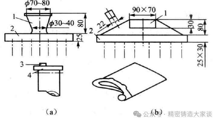
Figure 1 shows a steam turbine blade made of 1Cr13 stainless steel. Due to its relatively large size, serious bending deformation occurred when it was cast individually, with the blade axis deviating by up to 5 mm (against a specification of 0.8 mm). Initial attempts using a combined bottom-gating system as shown in Figure 2(a) did not eliminate the deformation. Subsequently, the scheme was modified to that in Figure 2(b), which successfully controlled the deformation within the specified limits. The key feature of option (b) is positioning the blade’s trailing edge close to the sprue, using the thermal energy of the metal in the sprue to balance temperature differences across the casting and slow down the cooling rate of the trailing edge, thereby significantly reducing deformation.
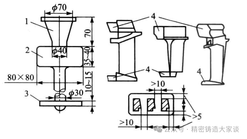
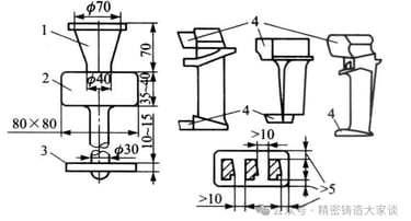
For turbine blades, square or rectangular cross-gates with side gating are generally employed (Figure 3). The upper cross-gate can be made thicker to also serve as a riser. Each cluster can include 6 to 12 blades. This gating system promotes directional solidification and feeding of the blades, facilitates cluster assembly, coating application, and cut‑off operations, and offers a relatively high casting yield. It is suitable for solid and hollow blades up to 160 mm in length. Since solidification starts from the exterior, a solid shell forms first around the casting after pouring. To enhance the feeding effect of the upper cross-gate, the ingate at the blade root should be positioned centrally, i.e., more than 5 mm away from the edge, as shown in the lower right detail of Figure 3.
Alternatively, blades can be poured with the root facing downward. In this case, the lower cross-gate and ingates should be larger. Compared with the previous orientation, this arrangement results in better grain structure but slightly inferior resistance to shrinkage porosity.
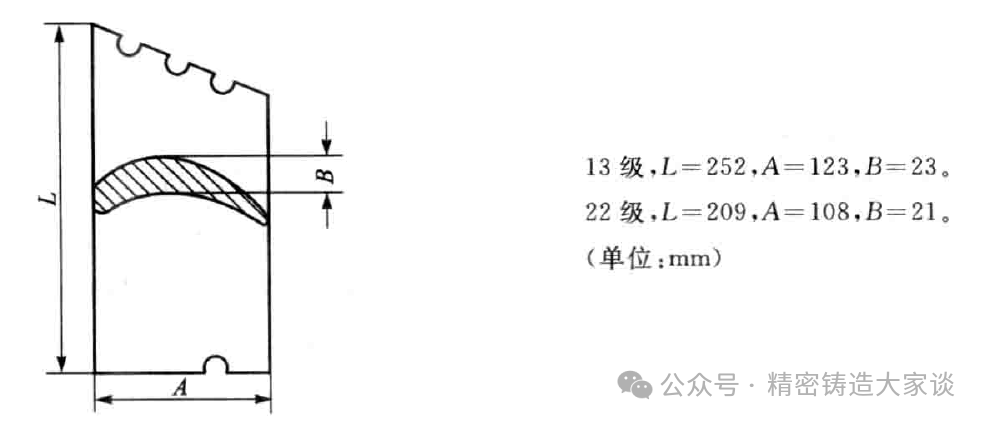
For guide vanes with a wide shroud (Figure 4), if the gating system described above is used—with ingates placed on the narrow side of the shroud—shrinkage porosity tends to occur at the transition fillet area because it is relatively far from the cross-gate. A better approach is to employ a single I‑beam side-gating system with the ingate located on the wider side of the blade, as illustrated in Figure 4, with 4 to 6 blades per cluster. This system retains the advantages of the previous one and is suitable for hollow guide vanes up to 130 mm in length where the lockplate thickness exceeds the blade body thickness, although the casting yield is somewhat lower.
The two gating systems mentioned above are primarily used under vacuum pouring conditions. Since atmospheric pressure is absent in vacuum pouring, these larger gate designs provide strong feeding capacity and help ensure casting quality. For blades without a shroud or lockplate, or with narrow and thin lockplates, top-gating through a cross-gate and ingate is preferable, as shown in types (a) and (b) of Figure 5. Such blades often include a sizable machining lug (10–20 mm high), which can also act as a riser. This gating system offers a very high casting yield and can be used for both vacuum and atmospheric pouring. The gate dimensions shown in Figure 5 are suitable for blades up to 100 mm in height and weighing less than 0.3 kg, with 6 to 8 blades per cluster. For vacuum pouring, larger cross-gate dimensions are recommended to ensure adequate feeding; for atmospheric pouring, they can be smaller. This gating arrangement works particularly well with tilt-pouring methods, yielding high‑quality blades.
Hollow blades are sometimes cast using a slit gate, which ensures smooth filling and favorable feeding conditions, though gate removal is more difficult.


Quality
Precision manufacturing for diverse industrial applications.
Services
Products
393055590@qq.com
+8615912702921